
There were some production issues with the kit I will discuss below, and the instructions were pretty worthless ("Connect wings. Connect tail..."). There was nothing on which screw went where, or how to setup the servos (setting up 90, setting the control rods and their connections to center the control surfaces, how to bind (or that you might even need to), how to use the Y connector for the aileron servos. But I managed with my rocket scientist IQ and my incredibly talent for building (as well as my stunning good looks). Its together, nothing broke, and the spare parts really have no place to go!
I inspected all the parts, and studied the tiny photos in the instructions to get some idea where this was going to go. I don't know if the factory bound the receiver and transmitter, so I did it with the included bind plug. Then I checked the movement and 90 on the rudder and elevator servos. I marked in the fuselage which was which (their rods apparently cross in the fuselage). Then I set to work on the build. I chose to work the tail first, then install the wing, though the instructions say to put the wing on first.

Box detail

Ginormous! Will have to build this downstairs on the big table.

Un-topped, see what's inside. Nicely packaged.
 .
. The parts pieces un-boxed. Not much to it.

Some genius at Exceed put a fighter jet glass cockpit in this Cub!

The bits.
No explanation for which thingy is going to go where. The Allen wrench isn't going to be used as an Allen wrench, but as a lever to secure the prop.

There is shrinkwrap over the short springs in the gear struts. Notice one is longer than the other. Underneath both springs are intact, quite short. Must have been being pulled on when it was shrink wrapped to give it room to expand. At least they could have done it evenly... You can see below the spring on the left that the strut itself is bent oddly... It's not stressed, it just was formed that way. Not very good QC on the gear assembly. Pushing the gear struts into place was very hard, especially since I didn't want to crush the fuselage, which is made of a strong specialized Styrofoam like material called EPO.

Close up of the uneven spring shrinkwrap and the oddly shaped gear strut on the left.

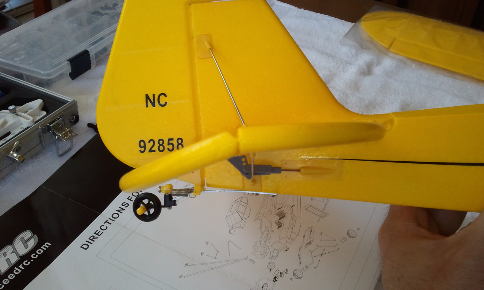
Another production issue. None of the control hinges would snap closed on the tail and stay closed. I will use a little heat to melt the plastic holding it closed before flight. I also had to use a longer screw from my heli kits, the big one on the lower right. This usually could be secured with 2 diagonally opposed screws (not that the instructions tell you that...), but there is a piece of the control surface hard plastic that sticks under the grey tower like thingy, tilting it and making it fairly unsecured. So I used 3 screws. But the problem area that lifted was that lower one so I had to put the big screw in. I used all long screws on the tail assembly with their thick wings.

Setting up the control surfaces on the tail. The servos were decently 90'd, but I had to loosen the control rods in the fuselage and set center on the elevator and rudder, then re-secure them. Pretty easy. I didn't spin the hinge on the end of the rod other than to center it cleanly. I had plenty of control rod to play with. I liked the way the connection to the servo is set up (see below) that allowed this easy setup. Check out the detailed tail wheel. Very springy for greaser landings!

Full up elevator. I have no idea if that is enough, and there is nothing about setting it up in the instructions. But as you can see it centers nicely, and equally deflects up and down. No binding in the servos to speak of, and no binding in any of the linkages. Easy peasy!
Full down elevator.

Close up, rudder linkage. No snap for you!

Now the wing. I did this after the tail, though the instructions said to put the wings on first. It would have been a pain moving the fuselage around working on the tail with the wings attached, so I put it off until I was ready. The servo wires are long (I think longer than stock servo wires... have think of that if I have to order new ones). They pass down a snug trench in the foam to the center. They are then passed down into the fuselage to the servo compartment. Its easy to see this when you put the model together. Checked the servos, wondering why only one worked at a time... Realized, "Hey... this is a four channel heli, I mean, airplane. Channel 5 doesn't do squat. I wonder if the Y harness is for the aileron servos?" Because, once again, nothing in the instructions. Turns out I was right. The servos get the same signal to deflect in the same directn, but are installed mirror image of each other so that the ailerons always move opposite each other. It doesn't matter which is right or left when plugging them in. Mine were correct (right roll input, right aileron up, left down, etc). If they were backwards I could probably reverse the aileron dip switch on the transmitter.

The servo and receiver compartment is open. You can see where I labeled R for rudder servo, E for elevator. The servos and their linkages, the control rods, and the Y harness can all be seen. The battery compartment is just to the right, with the vented cover. Wires are out of the battery compartment just so I could connect and disconnect power more easily during the build; they tuck cleanly inside the fuse. The black box at the top is the receiver. I wasn't sure if the antenna was supposed to be inside or outside the fuselage (fuse), which was long so made me think I did it right. I ran it out the back of the servo compartment and taped it to the fuse.

There was plenty of room for the receiver in the receiver box. I placed a trimmed piece of styrofoam from the shipping box to help hold the receiver and its wires in place so they didn't interfere with the servos. A single plastic wire tie secures the servo wires together as they come out of the servo compartment. the gray wire with the white end piece is the antenna.

Plugged in the aileron servos using the Y harness, once I realized something was amiss without it (only one servo moved until I used the harness. Doesn't matter which plugs into which, just make sure polarity is correct). Checked 90 on the servos, they were fine. Aileron linkage in the pic. I chose one small screw for the thinner trailing edge and one long screw for the ailerons thicker leading edge. The aileron hinge pieces snapped closed fine. Spun the hinges to fine tune center for the control surface at center stick.
Screwed the wing on, figured out how to take the spinner off, a little Locktite, prop in what seemed the proper direction, and voila, a Cub is born! Spin up showed I got it all right, lots of power! All the surfaces work well.
A few completed stock pics!


I love the detail on this plane, better than any of the others I saw out there.

Hung in the wall above my bench.Want to enjoy having her before I fly her and break her...


Yes, that's a HeliFreak sticker on my Plank!
Can't wait to fly!!!! Sim, Sim , Sim, then fly next week!
No comments :
Post a Comment