The entire nose was crushed and splintered, the motor mount/firewall disk shoved out of the opening, and there was nothing left to attach it to. I had idea how I was going to rebuild the firewall, hence I was also looking for a new fuse. CA'd things back into place and secured them with epoxy when I saw excess epoxy pooling in the nose. I realized I could mold a new firewall out of pure epoxy! So I taped her nose down on paper towel and poured epoxy in... You can see it pooling here.
Taped upright, left overnight to cure.
Some Bondo work to smooth things out.
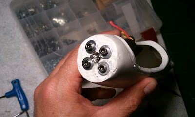
You can see the paper towel pattern in the firewall. I drilled out the mounting holes using the old motor mount disk as a template. I had thought about drilling out a circle and using the remaining flange for the motor mount disk, but thought this better since the new wall was thick.
I ended up replacing the box hex screws with flat screws to gain more clearance with the new prop spinner. These screws worked fine with the spinner, but were a bit long and protruding into the motor itself when screwed in. They cleared the motor rotor, but I had another option and liked it better.
This is what the motor looked like mounted before that change.
The tail rod had snapped off where it connected to the fuse. I cleaned this up and gave it a clean flat surface. I also redid the back shelf of the wing mount which can be seen on the left.
The tail rod fit sweet into the end of the fuse. Originally they were joined with a smaller cone of fiberglass that came out from inside the back of the fuse and fit inside the tail rod. I epoxied this and the next morning was initially pleased with how sturdy it turned out. Looked clean! But a few flexes and it was loose again. More on this later, because at this point it was working fine, but with handling came loose.
Had to build a tray for the servos. I needed to get everything lined up perfectly. The double center wood had to be cut out as the servos fit snug next to each other so their control arms clear the fuse. I placed with CA and secured with epoxy.The purple line delineates where the servo horns will be.
Here you can see the servos abut against one another. Underneath each abeam servo shelf is a 1 inch leg that gives each tray shelf 3 points of attachment. Barely room for the servo arms which run from the servo out towards the fuse.
During the above work the tail worked loose. I CA'd it in place properly aligned, but it had to be secured better. I thought of just using epoxy, but wasn't sure that would stand the flexing... so decided to use a 1 inch wide piece of fiberglass cloth to wrap around the joint. I used CA edges on the cloth to keep it from unraveling, which made it difficult to keep from unwinding from around the rod. Ended up using floss to wrap around the cloth to hold it in place while the epoxy ser. This was cosmetically unappealing, but certainly sturdy.
I sanded down the epoxy I used to soak the cloth once it dried and it was so uneven it looked horrible. I decided to Bondo the whole thing... can you see I have been making this entire process as I went along?
In the end I sanded down the Bondo and got a mostly smooth surface, but not good enough, so I covered it with black electrical tape and it looked great! I painted with gloss black lacquer the section of the tail rod CF that had sanding abrasions to clean it up. Sweet.
Nice work, if I do say so myself. Hopefully soon we will see how off her CG is... and see if she will fly! All her surfaces work and she has some mighty ailerons now! Still not impressed with the throw of the tail surfaces, but the servo control arms are so short to clear the fuse there isn't much more I can do. I shortened the control surface horns, and maxed the travel on the servos. Best I can do.


No comments :
Post a Comment