
The Walbro WA-80 carb arrived yesterday. I am using it instead of a replacement RCGF carb becasue I am curious what effect going from a 1-mm carb to a 7 mm carb might have on letting me lean out the mixture. Performance, efficiency and less oil all over evrything. It is new and unused, but its box had seen better days: apparently it's one of the last ones out there being Walbro no longer makes them. The WA-80 does fit, but there are a couple of unexpected challenges.

WA-80 on the left, stock RCGF one on the right. It's much smaller, but the faces are the same so it is compatible with the 10cc motor. The venturi is about 7mm but it cones down so on the outside air intake it is about 10mm.

The bottom. Very different here, and the first challenge. The throttle is on the opposite side. I do NOT want to move the throttle servo, so the WA-80 will be going in upside down. The RCGF throttle arm is the longer one. Note that it is desgined to be attached to a servo control arm, and can be removed to be replaced 180 deg. The smaller arm is the choke, which I had a manual control arm on, but never needed.

The top. Challenge number two is the throttle arm is not only on the wrong side, but it is designed for a throttle wire to move laterally across the carb, not fore and aft as on the aircraft servo control rod. How to I tranlate the servo fore-aft movement to lateral movement at the throttle arem? This throttle assembly can come out, but the throttle are is press-fit, not screwed on, so there is NO changing it. This about to beome THE major challenge and it will take a couple of hours to solve.

Removed the idle set screw.

Another view of the throttle arm. That idle screw post is gonna have to go. I Dremeled it off.
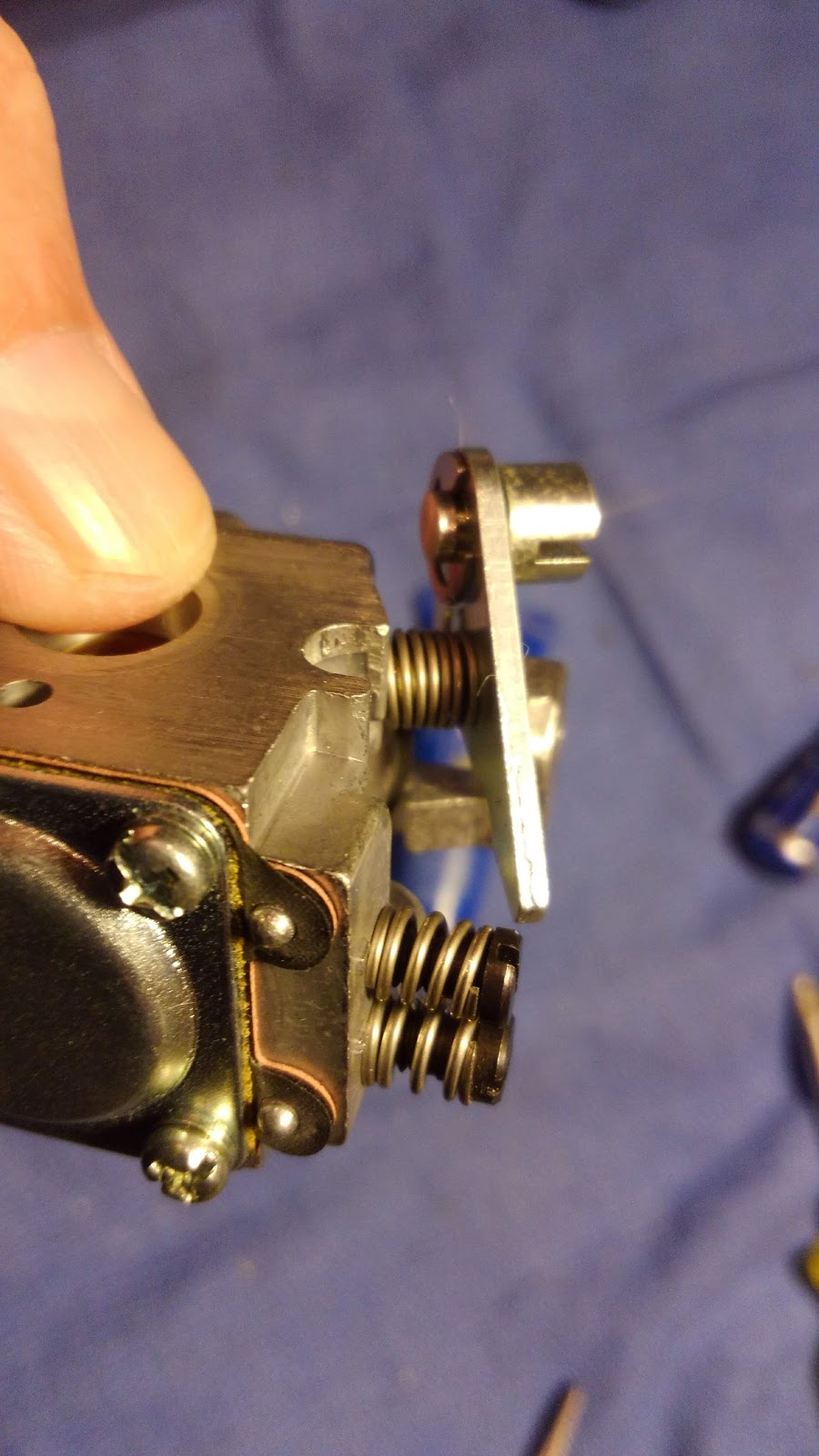
Another view of the throttle.

Test fit to see the lay of the land. The wire connector is removed and that large hole is where it was. The hole moves back and forth across the enging, not fore-aft, and the servo control are ain't going to go that way. I thought about how to use the existing linkages to translate the fore-aft to left-right. Nothing worked through the full throttle range. I was going to have to figure out how to attach a control arm on top of the throttle to change the geomety. No way to drill the steel...

I took an epoxy control horn since it is flat and figured out how to best fit it, then trimmed one side, and CA'd it in place. I was able to use two M2 screws and nylock nuts with rubber sided compression washers to futher secure it. It ain't elegant, but it would turn out to work quite well with a little shaping.

One of the screws is through the large hole the other is off one side of the throttle arm.

Another view.

Trimmed down.

Another view.

Engine installed. I would need to trim the servo arm to get full range of motion.

The "underside", installed this is the top. The fuel inlet is now on top, the needles inconveniently on the bottom.

View of the "top" which installed is underneath. Very busy in there.

With the control arm in place. I set it up so that I got range of motion from closed (where the throttle arm would have touched the idle screw arm) to full mechanical open (where the throttle stopped). The throttle in this configuration overshoots full open a few mm, so I need to remove the motor and mark the full open position. I did't think of this until I had installed it, as I had noticed it did this while toying with it while trying to figure out the control arm challenge. I would think it would have hard stops at both ends of the range.
I started working on this after I got home from work at 9pm, and stopped around midnight. This morning, if I get around to it, I plan to remove the engine and mark the real full range of motion, reinstall the engine and see if she will fire up. I will see where the needles are, they are clearly marked HI aft and LOW foreward, and that about 1.5 rotations would be a nice starting point. It comes with no manual.
If this carb is used on RC engines, the control arm would need to be redesigned and I would prefer it be screwed on rather than press fit allowing 180 degree re-positioning. While it would be more convenient to have the needles on the other side, this would require a major redesign. Most of us install the gas engines with the cylinder down due to the size and trying to maintain the scale appearance of the cowl on those aircraft with one. This makes having the needles on the "bottom" and throttle are on the "top" of the engine more convenient. When installed the needles are on top and the throttle underneath. This is without a choke, which is good because lordy there is no room for one.
We'll see how this goes! I will update this post, not make a new one.
UPDATE 1:

Air inlet.

Air inlet, throttle leaflet.

Clean look on top.

A close view of the needles. Clearly marked high/low. I put a touch of silver on a corner to mark their location. Each was about 1-1/4 turns out. Nice place to start.
I checked the ROM and the full that I have takes it from the actual full to closed just fine. Lots of distance, should allow for a nice range of speeds with good resolution.

IT WORKS! IT WORKS!
Listen to that. LISTEN TO IT! That is the sound of success! It took about 45 min of tuning about the default setting to find the sweet spot. When they say "screw driver blade width" adjustments, that's what this baby needed. A little too much or not enough changed everything. The high needed very little tweaking. I didn't have the tach set up, but she idled wonderfully without thrust, and ran WOT clean with that sound I know is her max. Transition was sweet with fine resolution, more than this plane and pilot needs. She idled forever, and it was nice to have to use the ignition cut-off to stop her. I ran her over and over again with the same results, so I am pretty sure she is solid. I need to get her in the air to see how she handles altitude and orientation changes, loading and unloading. I am not sophisticated enough to say, but between lowering the servo speed to one second and this smaller carb, she transitions a lot smoother than before. She is back to being a good engine! I am a happy boy!

I knew she would need to be primed from dry, and couldn't fit my finger back behind the engine to cover the air inlet. I made a little thing and it worked first turns.

Going into position.

Obstructing the air inlet. Only had to do this with the first start, now that the carb is wet shouldn't be a problem, but I will keep this stick in the field box.

Another thing I did notice performance wise, and this was one of the goals. No fuel oil all over the plane. She ran smoother, less four-cycling, and this clean look support that she is running much leaner!
I think this experiment is a success! For production she would need a few design changes, but nothing internally, all easy stuff. This smaller carb may be the way to go!
Read your blogs with interest as I recently purchased a rcgf 10cc and have challenges tuning it. Mine came with a walbro wt1183 carb. Am I correct in that your stik has been fitted with a wa80a and that your sukoi has the rcgf upgrade carb with needle settings of 3-4 turns, and that you're happy with how both rcgf 10cc engines run?
ReplyDeleteSorry, I have realized I have forgotten to check for comments!
ReplyDeleteI do love these engines. 10cc engines are needy, but these RCGF-USA ones are the best. Don't buy from Valley View, though, make sure you have a real RCGF-USA engine.