The Hangar 9 Ultra Stick 10 cc project is done, and it was some kind of journey. I've not had a build shift course so many times. Its not where I was going, but its where I intended it to be.

It started out straight forward enough. This was the original design of the equipment bay. This was based mostly on the ginormous reciever/ignition battery, a 2S 5200 mAh LiPO I had bought for the test bed, but instead decided to use it on the Stick. Its weight is about the same as two 2500 mAh NiMH batteries. Its a hard case battery, and its size limited options for the other equipment. I couldn't use the standard size cut out that runs across the fuse at the front of that tray because the battery covers it. I was planning to use a mini servo for the throttle, and had to chisle out a mm here and there to get that to fit. You will notice there is no throttle control rod. At this point I wasn't sure how this was going to work. This plane was designed around the now discontinued Evolution 10 cc engine that I am using, but I am not sure where they thought the control rod was going to go through the firewall straight to the throttle. Was planning to solve that problem later. Even then it wasn't going to be straight, as you will see below. The satellite is forward on the starboard side. None of this plan would survive first contact with the enemy, except the reciever.

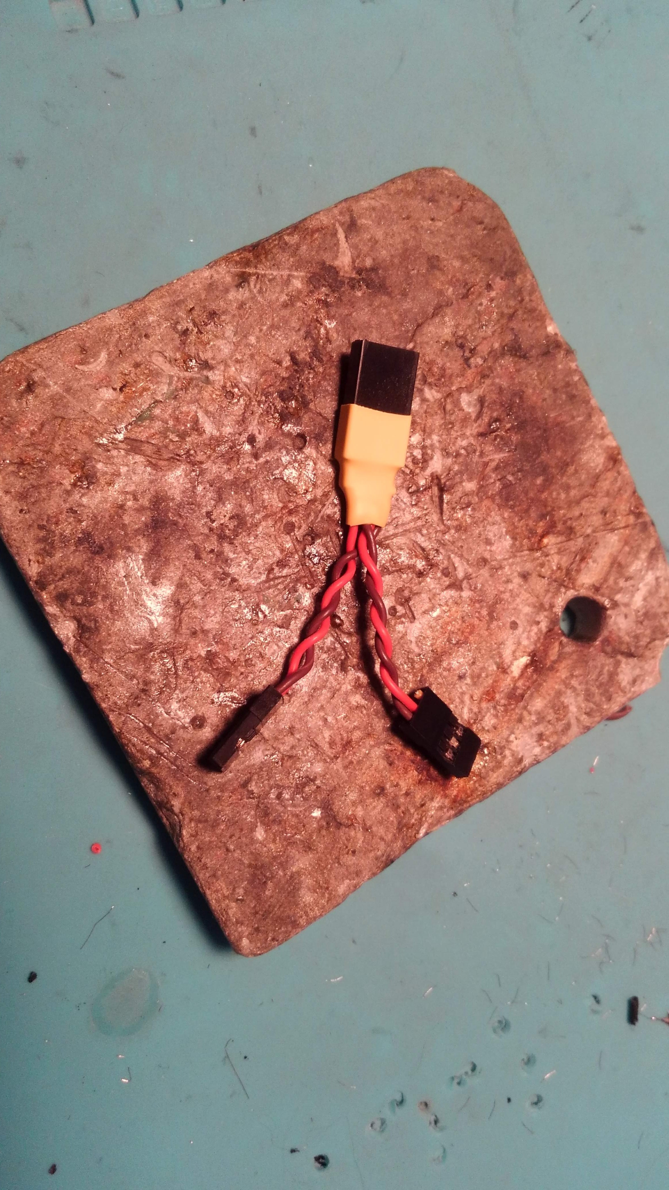
This original design survived. I made this connector to allow a single output from the battery to split to the ignition and receiver electric switches. I had soldered a single Futaba connector to the main leads of the battery. This resulted from my having to cancel the order of the Hobby King Turnigy Battery Switch as by day 8 it still hadn't shipped, instead I went with the dual Miracle switch I had on hand.
This is the battery harness in place on the switch.
I was now going to have trouble placing the switch. It was going to need me to move the battery out of the way, but there is no room for that, unless I cut the deck and allow it to rest on the bottom. Remember that everything forward of the servo on the port side is reserved for the control rod. Initially I planned to lay it flat under the deck, but there was no way to get it in there. I changed the idea again and decided to make it lay vertically. The landing gear hard point would be under the front, so it will be angled, but the highest part, forward, would still be under the wing that forms the top of the compartment.
So, I made a vertical tray. Since the battery is a hard case, and its a 80C only running a receiver and ignition it will never puff, so close quarters are fine. Not really sure what happens when hard xase batteries puff...
To give it a clean look I painted it black.
Looking good. I still wasn't quite sure how the switch was going to fit, or where.

While that was drying, I moved to the landing gear. This is a sturdy metal tail gear assmebly I used for two reasons. I had gone back and forth between using the stock straight plate with it's connection to the rudder, a design that can put a lot of stress on the rudder hinges as the plate doesn't completley protect them from jostling forces on the gear shaft, transmitting them to the rudder and therefore the hinges. Also, I am using the big wheels from the Ugly Stick, so the low set stock tail assembly would lead to a bit more angulation of the fuse and endanger a rudder strike. Lastly, I wanted something sturdy. The reason I like the larger wheels on both Sticks was to allow it to fly off rough surfaces, as when I first flew the Ugly Stick it was off the clumpy grass at the Bedford field that claimed so many landing gear. Flying off that rough a surface won't be much of an issue now, but I do like the look.
Here she is, on her wheels for the first time.
The engine installed. I removed the two muffler extension pieces that were needed to get the muffler out of the wide Sbach cowl, and she is back to stock configuration.
I made a fuel vent. I don't know why these are so hard to find. I don't like a simple tube running down. Here I used a fuel dot rim, and a clunk with a flat bottom that I JB Welded to one another. The clunk just happened to fit in the rim! Came out swell!
I want the satellite to be aligned vertically. In the equipment bay it was going to be severely blocked by the battery. I decided to move it aft as far as I could. I can't get back there easily so I came up with the idea of putting it on a boom and getting it back there.
You can see the satellite block aft of the reciever here. Its set on a platform I made using Dual-Lock velcro. Here you can see the switch in place. I used the stock switch cut out on the port side, enlarged it a bit. You can see how the switch is kinda deep and would not fit on the starboard side. You still see the mini servo...
So this is where the bay layout stood for a few minutes. It is packed. Still working on ideas for the control rod at this point.

With all the angulation back and forth in the control rod path, I figured the only way I would get something to work was to use braided wire, its flexibility making it a working solution. After several tries I managed to solder the Du-Bro linkage to the wire. In practice however, the final path took a sharper angle at the end near the throttle than the wire would allow making it too flexible at a point that elbowed, transferring the movment to flexing insetad of to the throttle linkage. I tried hardening it with solder, but that only partially solved the problem. I decided to try a softer, smaller diameter flexible solid control rod. That worked better than I had tought. I changed the throttle control rod connection as well as I couldn't get the Du-bro connector to solder to the rod. I did have to drill a new passage throught the firewall taking the engine mounts into account, making for a straighter path. New problem: the micro servo was working with both designs, but taking a lot of strain to do so due to friction in the path. It was going to need a standard servo.

Here the standard servo is in place. Once again had to do more cutout in the already trimmed out servo tray. and build up the servo hardpoints. Here you can see the control rod in place. I used two pieces of thin plywood to create a hardpoint as the rod passes into the guide tube. This stiffened the path so the softer control rod could would be more efficient in transfering the movement to the throttle.
Here I had to remove the engine and mounts to drill a new pass through hole through the firewall to creat a straighter path. The engine still blocks the path, which as you can see below, required a cut out of the mount strut itself to keep a sharper S curve out. Epoxied this in place,, but the firewall is almost a cm thick. I could have drilled a hole into the mount from behind, but I didn't think of that until now... I will go back and do that, I think.
Here is where it passes throught the firewall on the engine side. I had to grind a big dent in the engine mount strut to allow it to weave pass the base of the engine. It remains hard against both but more or less straight. The stock design has the engine upside down as I do it, so I have no idea how they connected this.
You can see the tank is as far to starboard as I could make it. The path is pretty much straight now, except after it passes the firewall and runs into the engine. The ignition is in a small bay directly underneath.
All up! Did the programming last night into the iX12. Need to set the CG and weigh her. All in all I am quite pleased and hope she flies well!
Hangar 9 10cc Ultra Stick ARF. Evolution 10cc gasser, Evolution CDI Ignition, with a 13x8x3 Master Airscrew prop under an aluminum spinner. RCExcel optical ignition remote cut out. Zeee 7.4V(2S) 5400 mAh LiPO receiver/ignition pack in a hard case, from Amazon ($17 shipped!). Miracle power switch. Spektrum AR7010 receiver with one satellite. Sullivan 4" tires. Don't know the make or source of the tail assmebly, but its for a 50cc aircraft and easy to find as there are so few options out there. Could find a decent one for 10cc 0r 60 sized airplane.